
Integrating Sensors into Harvesters: Placement, Calibration, and Data Flow
TIME
Click count
Successful sensor integration for harvesting depends on three connected decisions: where a measurement represents the crop process, how it will be calibrated under operating conditions, and how its data reaches the system that uses it. A sensor can perform correctly on a bench yet produce misleading yield maps or unstable control signals once vibration, dust, changing crop flow, and communication delays enter the picture.
Start by defining the decision each measurement must support. An operator warning, a field record, and an automatic machine adjustment require different response times and failure handling. Establishing those requirements before selecting hardware prevents expensive changes during field commissioning.
Define the measurement before choosing the sensor
“Measure crop flow” is too broad to serve as an integration requirement. The specification should identify the physical quantity, operating range, required accuracy, allowable delay, and conditions under which the reading becomes invalid. It should also name the independent reference used to judge performance.
Keep the initial scope tied to operational outcomes. Yield mapping generally needs crop mass flow, moisture, position, travel speed, and effective cutting width. Monitoring machine condition may instead depend on bearing temperature, vibration, and shaft speed. Automatic adjustment adds requirements for stable feedback and predictable response.
The discussion below focuses on grain combines. Other harvesters share the same integration principles, but their measurement points differ. A forage harvester, for example, requires a sensing approach suited to chopped material moving through its feed and discharge systems.
Assign ownership for each derived value. If one supplier calculates wet yield and another converts it to dry yield, both must use agreed units, moisture definitions, and reference conditions. Otherwise, individually plausible readings can produce inconsistent totals.
Place sensors around the material path
Sensor placement should follow the physical process. Identify where material enters, changes direction, separates, accumulates, and exits. Then consider whether the proposed location sees a representative sample or a local disturbance.
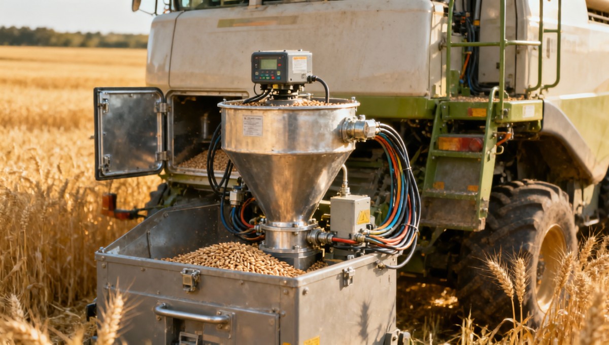
On combines that use impact-based grain-flow sensing, the sensor typically measures force as grain leaves the clean-grain elevator. Its relationship to the discharge trajectory matters: changes in elevator speed, impact geometry, or material buildup can alter the signal without a corresponding change in harvested mass. Preserve the specified geometry and provide access for inspection.
A moisture sensor needs consistent exposure to representative grain. A location that collects fines, retains old material, or experiences intermittent filling can bias the reading. Where a bypass sampling arrangement is used, verify that grain enters and clears it reliably across expected flow conditions.
Loss sensors require a different interpretation. They detect impacts associated with material leaving the separation or cleaning system; they do not directly count every lost grain. Mounting position, crop type, residue, and vibration affect their response. Use them to track changes after adjustment, with field loss checks supporting interpretation.
Position data also needs physical context. Record the GNSS antenna’s offset from the header and the machine reference point. Include header engagement and effective cutting width in the data model. A precise antenna position cannot correct a yield calculation that assumes a full-width cut during partial passes.
Design the mounting and wiring together
A suitable sensing point may still be a poor installation point if a bracket flexes, a cable rubs against a guard, or routine cleaning becomes difficult. Check clearance through the full movement of headers, folding sections, and service panels. Route harnesses away from hot surfaces, moving components, and likely crop accumulation.
Mounting stiffness should match the measurement. A vibration sensor needs a repeatable mechanical connection to the component being monitored; a flexible cover may mainly reveal the cover’s own motion. Other sensors may benefit from isolation against unwanted vibration, provided that isolation does not interfere with sensing.
Select connectors and enclosures for actual exposure, including dust, moisture, cleaning practices, and agricultural chemicals. Environmental ratings alone do not establish compatibility with every washdown method or fluid. Provide strain relief, accessible connectors, and clear identification so replacement does not introduce wiring mistakes.
Calibrate the installed measurement chain
Calibration must cover the complete chain: sensor, mounting, signal conditioning, conversion settings, and software calculations. A factory-calibrated component does not establish the accuracy of the assembled harvester system.
Begin with mechanical and electrical checks. Confirm mounting geometry, supply voltage, grounding, channel identity, and configured units. Record the unloaded response where applicable. Calibration performed before correcting a loose mount or unstable supply can hide a fault inside the adjustment coefficients.
For yield measurement, use independently weighed crop loads and align their boundaries with the machine records. Account for material remaining in the machine or grain tank when defining a comparison. A reference load is only useful when it corresponds to the same material represented by the sensor data.
Include the operating conditions expected in use. A single load at steady, moderate flow may not reveal errors at low throughput or near the upper working range. Follow the calibration procedure appropriate to the sensing system, then validate across relevant crop flow, moisture, and machine conditions. Keep calibration loads separate from validation loads so acceptance measures performance on independent data.
Moisture readings should be compared with an appropriate reference method using representative samples taken close to the sensing event. Differences in sampling time, sample handling, and temperature can otherwise look like sensor error.
Store calibration versions with their crop, machine configuration, date, and applicable conditions. Recheck performance after changes that affect the measurement path, such as elevator work, sensor replacement, altered mounting geometry, or a substantial change in crop characteristics.
Align time, crop movement, and field position
A common yield-mapping error occurs when a valid grain-flow reading is attached to the wrong location. Crop takes time to travel from the header to the flow sensor. Meanwhile, position updates, network transmission, and software processing introduce additional delays.
Treat crop transport delay and electronic delay separately. Transport delay follows material movement through the machine and may change with operating conditions. Electronic delay comes from sampling, buffering, communication, and processing. Combining both into an unexplained correction value makes diagnosis difficult.
Where supported, timestamp measurements near acquisition and preserve those timestamps through the data pipeline. Record the time source and clock synchronization status. The receiving application should be able to distinguish when a measurement occurred from when its message arrived.
Validate alignment during transitions: entering crop, leaving crop, stopping, and restarting. A map may look convincing during steady travel while placing yield incorrectly at headlands. Header state, travel speed, effective width, and delayed crop flow must be interpreted together. Define how the system handles a stop while material is still moving through the harvester.
Build data flow around the required response
A practical architecture separates acquisition, onboard processing, operator display, local storage, and remote transfer. Each stage should have a defined role. Functions requiring timely machine response should operate onboard, while remote platforms can support reporting, fleet analysis, and historical comparisons.
Use the machine’s supported interfaces where available. CAN-based communication is common on agricultural equipment, but connecting to a bus does not guarantee access to a usable signal. Message definitions, units, update rates, source identification, and diagnostic behavior must be agreed. ISOBUS compatibility likewise does not guarantee that every desired measurement is exposed to every connected application.
For retrofits, establish the permitted interface with the machine supplier. A supported gateway may simplify access and fault separation, while direct sensor acquisition may suit equipment with limited electronic interfaces. The choice depends on signal availability, required timing, installation effort, and maintenance ownership.
Every record should retain enough context to remain meaningful beyond the display:
- The measurement value, unit, acquisition time, and source identity.
- A validity state that distinguishes usable data from stale, missing, or out-of-range readings.
- The applicable calibration or configuration version.
- The machine and work context needed to interpret the measurement.
Do not convert a communication failure into a plausible zero. Zero crop flow and missing crop-flow data have different meanings. Similarly, repeated transmission of the last valid value must not make a disconnected sensor appear healthy.
Store data locally when field connectivity is unavailable, then synchronize it with clear rules for retries and duplicate handling. Define buffering capacity against the expected disconnected operating period. Protect configuration changes and remote access, and keep a record of changes that affect measurement interpretation.
Make commissioning expose likely failures
Commissioning should demonstrate that the system supports its intended decisions across realistic conditions. A dashboard displaying values establishes connectivity; it does not establish measurement quality.
Agree acceptance criteria before field trials. Set tolerances according to the use case and express how they will be measured. Total harvested mass agreement alone is insufficient for yield mapping because positive and negative local errors can cancel. Assess spatial alignment, short-term behavior, and total mass separately.
- Check the stationary installation. Verify wiring, channel mapping, unloaded readings, configuration, and diagnostic messages.
- Operate the machine without crop. Look for false flow, vibration interference, speed-dependent offsets, and electrical disturbances.
- Run controlled harvesting comparisons. Use independent references and include representative flow conditions.
- Test transitions and interruptions. Examine partial-width cutting, header lifts, stops, restarts, and loss of remote connectivity.
- Introduce recoverable faults. Disconnect a sensor or interrupt a permitted interface and confirm that displays, records, and dependent functions respond as specified.
Inspect raw and processed signals together. Filtering can make a display easier to read while delaying a response or hiding intermittent faults. Retain enough diagnostic information to distinguish a physical process change from a sensor, wiring, or software problem.
Turn the field trial into a repeatable operating procedure
Handover should include installation drawings, connector assignments, signal definitions, calibration procedures, software versions, and acceptance records. Assign responsibility for sensor faults, gateway configuration, derived calculations, and platform imports so failures do not become disputes between suppliers.
Provide a short pre-harvest check covering sensor cleanliness, mount security, harness condition, position reception, active calibration, and local recording. Explain which maintenance actions require a calibration check and how operators should respond to degraded data.
The next practical step is to document one measurement from its physical source through to its final use. Specify its mounting point, independent reference, timing, validity rules, and failure response. Once that path is clear, repeat the process for the remaining signals. This gives installation, software integration, and field acceptance a shared basis for deciding whether the system is ready to harvest.
Recommended News
- What Excavator Hydraulic Specs Matter for Tropical Terrain?Oct 27, 2026Compare excavators hydraulics specs for tropical terrain, from pump flow and cooling to filtration. Discover what keeps machines productive in heat and rain before you buy.
- Integrating Sensors into Harvesters: Placement, Calibration, and Data FlowOct 27, 2026Improve sensor integration for harvesting with practical guidance on placement, calibration, and data flow. Learn how to achieve reliable yield maps and dependable machine control.
- Tracked or Wheeled Excavators: Which Should You Choose for Muddy Sites?Oct 12, 2026Should I choose a tracked or wheeled excavator for muddy sites? Compare traction, ground pressure, safety, and project costs to select the right machine with confidence.
- Heavy Equipment Sourcing: A Due-Diligence Checklist for Reliable SuppliersOct 06, 2026Heavy equipment sourcing information: use this due-diligence checklist to verify suppliers, compare true costs, control delivery risks, and secure reliable equipment support.
- What to Evaluate When Selecting a Radiator Manufacturer for Heavy-Duty EquipmentSep 27, 2026Radiators manufacturer selection guide for heavy-duty equipment: evaluate thermal performance, durability, quality control, supply reliability, and lifecycle value.
All Categories
Hot Articles
- Audience Targeting for Regional Cultural Promotion: A Practical GuideNov 16, 2026Master regional cultural promotion audience targeting with practical tips to reach the right people, craft compelling messages, and drive participation.
- Oman Awards Two Duqm Green Hydrogen Projects and Opens Fourth Auction at COP31Nov 15, 2026Oman green hydrogen projects in Duqm target 121,000 tonnes annually by 2032. Explore the awards and a new auction linking hydrogen with green-powered data centers.
- Supplier Capability Metrics: How to Assess Capacity, Quality and DeliveryNov 15, 2026Use supplier capability metrics to assess capacity, quality and delivery. Learn how to verify claims, compare suppliers and reduce sourcing risks.