
Sizing an automation and power distribution system for future demand starts with credible expansion scenarios, measured operating data, and clear limits for capacity, reliability, and cost.
A blanket spare-capacity percentage rarely addresses every constraint. Transformer loading, fault duty, feeder capacity, control performance, and physical expansion space require separate engineering decisions throughout planning.
For technical evaluators, the strongest design demonstrates how each growth scenario affects equipment ratings, operating conditions, protection settings, and upgrade timing before major procurement commitments occur.
The objective is to install sufficient capacity where later replacement would be disruptive, while preserving practical expansion options where additional equipment can be introduced economically.
What future demand should the design actually support?
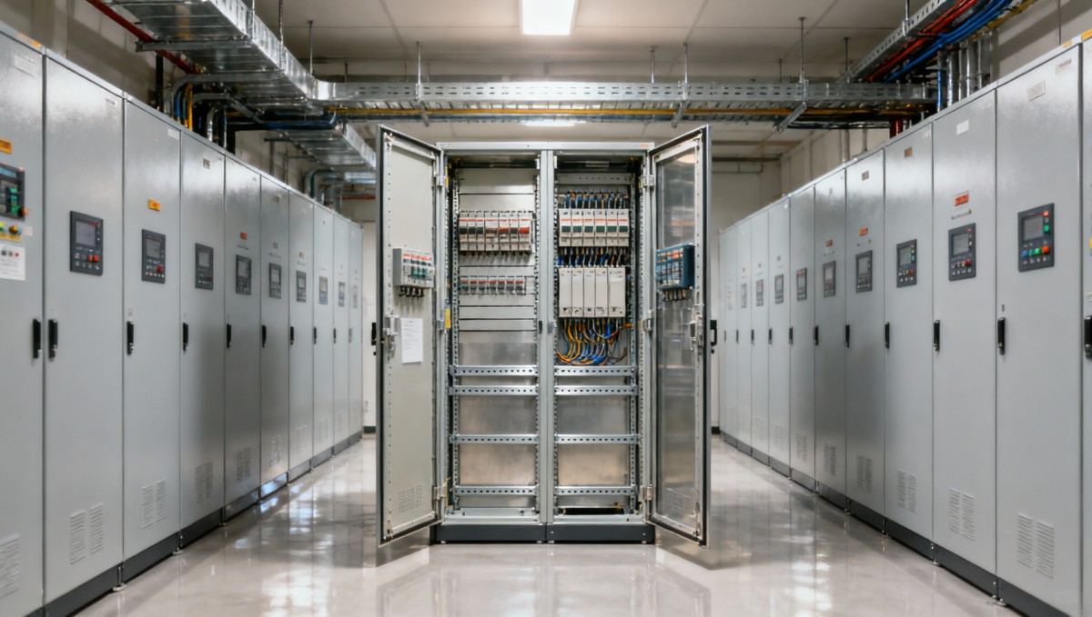
Begin with a load register that distinguishes installed nameplate capacity, measured demand, expected additions, and uncertain projects. These categories should remain visible throughout the evaluation.
Record voltage, phases, rated power, power factor, operating schedule, starting method, criticality, and expected commissioning date for each significant load, including planned process equipment additions.
Build at least three scenarios: current operations, committed expansion, and plausible longer-term growth. Assign dates and assumptions so speculative demand does not silently become mandatory capacity.
Each scenario should describe operating combinations, including peak production, maintenance, seasonal heating or cooling, and restart after an outage. Different combinations can govern different equipment.
Use interval metering to identify coincident demand and operating patterns. Supplement utility records with shorter-duration measurements where motor starts, welding, or rapid cycling may matter.
Document the measurement period and missing operating conditions. Data from a lightly loaded month cannot establish the credible maximum demand of a seasonally intensive facility.
A useful scenario register records each assumption’s evidence, owner, confidence, and review date. This makes later scope changes traceable and prevents margins from accumulating invisibly.
How do connected loads become a defensible design demand?
Connected load is the sum of equipment ratings; design demand represents credible simultaneous operation. Confusing them can produce either expensive oversizing or inadequate operating capacity.
Apply demand and diversity factors only where operating schedules, measurements, or process constraints justify them. Two production lines sharing one bottleneck may behave differently after expansion.
Keep units consistent. Kilowatts describe active power, while kilovolt-amperes describe apparent power; transformers and many distribution ratings depend on apparent power and current, not kilowatts alone.
For balanced three-phase loads under suitable conditions, apparent power equals active power divided by true power factor. Current then follows from apparent power and line-to-line voltage.
- Apparent power: S (kVA) = P (kW) ÷ power factor.
- Three-phase current: I (A) = S (kVA) × 1,000 ÷ [√3 × V (V)].
- Evaluate unbalanced loads by phase; aggregate three-phase totals can conceal an overloaded conductor.
For nonlinear loads, distinguish true power factor from displacement power factor. Harmonic current can increase heating even when a conventional reactive-power calculation appears to indicate adequate capacity.
Separate sustained demand from transient requirements. A brief motor start may govern voltage-dip performance without determining the transformer’s continuous thermal rating under normal operating conditions.
What does a practical transformer-sizing calculation look like?
Consider a facility with measured coincident demand of 850 kW and a committed expansion adding 350 kW during the same operating period under the forecast scenario.
The projected demand is 1,200 kW. At an assumed true power factor of 0.92, the corresponding apparent demand is approximately 1,304 kVA before further allowances.
If the project adopts an illustrative 80% planning utilization target, the calculated transformer capacity becomes approximately 1,630 kVA. This target is an assumption, not a universal requirement.
A locally available 2,000 kVA transformer could therefore enter the shortlist. Its suitability still depends on ambient conditions, cooling, harmonic loading, impedance, and expected operating cycles.
At 400 V, the forecast demand corresponds to approximately 1,882 A, while a 2,000 kVA transformer’s rated secondary current is approximately 2,887 A under balanced conditions.
These values inform different checks: expected loading supports operating assessment, while equipment capability, protection, and applicable rules determine busbar and feeder requirements for the selected arrangement.
Compare candidate sizes using capital cost, no-load and load losses, maintenance, and upgrade disruption. Excess capacity has economic consequences even when electrical performance remains acceptable.
Which limits can invalidate an apparently adequate power rating?
A transformer with sufficient kVA does not guarantee acceptable voltage. Evaluate steady-state voltage drop and transient dips at sensitive loads under the relevant operating scenarios.
Motor starting, transformer energization, and simultaneous restart can create distinct disturbances. Model starting methods and restart sequencing before assuming that a larger transformer solves every issue.
Variable-frequency drives, rectifiers, and other nonlinear equipment require harmonic assessment. Review transformer heating, neutral loading, capacitor resonance, and any filtering requirements against the expected spectrum.
Size cables using installation method, ambient temperature, grouping, insulation limits, and applicable rules. Then verify voltage drop and short-circuit withstand for the selected conductor arrangement.
Future expansion can also increase available fault current. Check switchgear interrupting ratings, assembly withstand ratings, and protective-device duties for every credible source and bus-coupler configuration.
Revisit protection coordination as equipment changes. Selectivity, fault-clearing time, equipment damage limits, and arc-flash exposure can interact, requiring documented tradeoffs rather than isolated setting changes.
Where should spare capacity be installed, and where should it be reserved?
Separate electrical headroom from physical expansion provisions. Spare transformer capacity, spare feeder ways, empty panel space, and available cable routes solve different future constraints independently.
Prioritize provisions that become difficult to add after commissioning: switchroom space, access routes, foundations, cable trenches, busbar arrangements, and safe clearances for equipment replacement or extension.
Install additional active equipment when its expected use and lead time justify the investment. Otherwise, reserve interfaces and space while defining a practical installation trigger.
For each major component, document its rating, forecast loading, permitted operating limit, expansion method, and replacement consequences. A single facility-wide spare percentage cannot communicate these differences.
Use staged expansion where uncertainty is high. A second transformer bay or sectionalized distribution arrangement may preserve options, provided future switching and protection requirements are resolved.
Confirm that expansion work can occur safely within acceptable outage windows. An unused switchgear compartment offers limited value if connecting it requires an unacceptable facility shutdown.
Will the automation infrastructure scale with the electrical system?
An automation and power distribution system needs coordinated capacity planning. Adding electrical feeders can increase I/O counts, communications traffic, historian storage, alarms, and controller processing demand.
Forecast digital and analog I/O separately, including signal types, isolation, safety functions, and cabinet locations. Spare channels are useful only when their characteristics match future instruments.
Evaluate controller execution time, memory, communications connections, and network utilization under expansion scenarios. Large unused memory does not guarantee adequate scan performance or acceptable response time.
Reserve cabinet space and cooling capacity for future modules, switches, and power supplies. Check enclosure heat dissipation and the impact of added equipment on environmental ratings.
Size control power and UPS systems for defined operating needs, including ride-through duration, battery aging, ambient temperature, and safe shutdown. Avoid applying arbitrary runtime margins.
Define address allocation, network segmentation, time synchronization, and integration standards early. Expansion should preserve manageable cybersecurity boundaries and predictable communications behavior across controls and electrical monitoring.
How do reliability requirements and distributed energy change the answer?
Define the required service level before selecting redundancy. Identify which loads must continue through a component failure, which may pause, and which can be shed.
Two transformers do not automatically provide N+1 capacity. After one unit fails, the remaining arrangement must support the defined essential demand within its allowable operating limits.
Check contingency loading alongside switching arrangements, transfer timing, maintenance access, and common failure points. Redundant capacity has limited value when one shared dependency disables both paths.
Solar generation and battery storage require scenario-specific treatment. Their contribution to peak reduction depends on output, state of charge, controls, availability, and the required service commitment.
Do not automatically subtract renewable nameplate capacity from future demand. Evaluate import, export, charging, and islanded operation separately wherever those operating modes are part of the project.
Inverter-based resources can change fault behavior and protection sensitivity. Verify grounding, islanding controls, and protection performance against actual equipment characteristics rather than conventional generator assumptions alone.
What evidence should technical evaluators require before approval?
Request a design package that connects assumptions to calculations, equipment selections, and operating limits. Reviewers should be able to reproduce the main capacity decisions independently.
- A dated load register and scenario matrix with documented coincidence assumptions.
- Single-line diagrams showing current equipment and planned expansion arrangements.
- Load-flow, short-circuit, protection-coordination, and relevant power-quality studies.
- Cable calculations and equipment derating assumptions.
- Automation capacity budgets and control-power calculations.
- An expansion sequence with outage requirements, costs, and decision triggers.
Apply the relevant local code, utility requirements, and equipment standards. IEC and North American practices differ; a component rating alone does not establish installation compliance.
Define commissioning acceptance criteria before purchase. Include representative load testing, protection verification, communications checks, and restart sequences appropriate to the facility’s operating requirements and critical loads.
After commissioning, trend demand, phase currents, voltage, harmonics, equipment temperatures, and automation utilization. Link observed thresholds to procurement lead times so upgrades occur before constraints become operational.
Conclusion: approve an expansion path, not just a larger rating
A future-ready automation and power distribution system combines defensible demand forecasts, verified electrical performance, scalable controls, and practical expansion provisions. Each element addresses a different constraint.
The strongest sizing proposal explains what can be added, under which operating conditions, and when another investment becomes necessary. That clarity supports both technical approval and disciplined spending.
Choose capacity through scenario-based analysis, then preserve the space, interfaces, and operating flexibility needed for growth. Measured evidence and explicit limits make future expansion manageable.