
Linking industrial automation and power distribution to cut downtime
TIME
Click count
A highly automated production line can still stop when a brief voltage dip trips one critical drive. Linking industrial automation and power distribution reduces downtime when electrical events become visible to the control system, protection isolates faults without unnecessarily disconnecting healthy equipment, and recovery follows a validated sequence. Connecting devices to a shared dashboard is not enough.
The practical objective is to control the full interruption chain: what initiates a disturbance, which loads stop, what remains operational, and how production returns safely. That requires electrical design and automation logic to be developed together, with clear ownership of the interfaces between them.
Start with the failure chain, not the communications network
A production interruption can begin upstream of the machine displaying the alarm. A voltage sag may trip a variable-frequency drive, release a contactor, or interrupt a control power supply. The resulting loss of conveyor motion can then generate downstream alarms for missing material, blocked equipment, and sequence timeouts. Investigating only the final machine alarm can leave the electrical cause unresolved.
Before specifying gateways or monitoring software, map the electrical supply path against process dependencies. The electrical single-line diagram shows how power reaches equipment; the process sequence shows why the loss of one item stops others. Neither view alone identifies all production-critical loads.
A small lubrication pump, cooling circuit, network switch, or control power supply can be more important to line continuity than a much larger motor. Criticality should therefore reflect production consequences and recovery time, not simply load rating.
This mapping also defines the limits of integration. Monitoring cannot correct inadequate fault ratings, damaged connections, insufficient supply capacity, or a machine that cannot tolerate the disturbance being measured. It provides evidence for choosing the appropriate intervention.
Capture electrical and process events on a usable timeline
The most valuable shared view combines electrical conditions with equipment state. Useful signals include feeder voltage and current, breaker position and trip indication, drive fault codes, control-power status, and the operating state of dependent machines. Each signal should answer a diagnostic or operational question; collecting every available register adds complexity without necessarily improving recovery.
Measurement capability matters more than the number of connected meters. Energy data collected at relatively slow intervals will not explain a short voltage sag. Where brief disturbances are suspected, instruments need suitable event capture, waveform recording where justified, and retention settings that preserve the evidence after an incident.
Time synchronization is equally important. If the power meter, programmable logic controller, and supervisory system use different clocks, the apparent alarm order can misidentify the initiating event. Specify timestamp accuracy according to the event being investigated, including whether timestamps originate in the device or are added when a server receives the message.
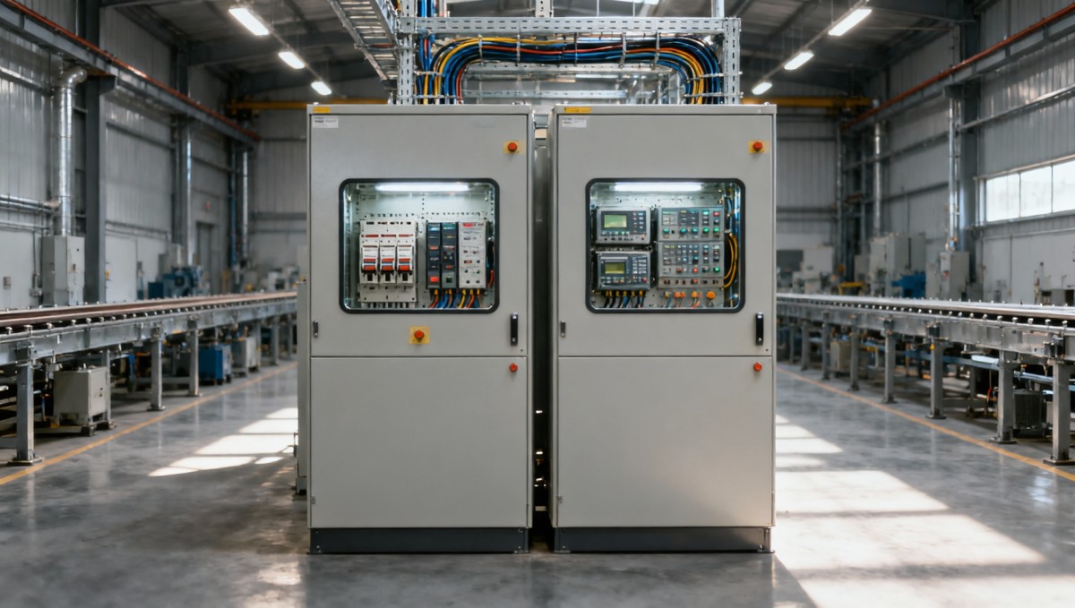
A useful integration view traces the incoming supply through switchgear and motor control centers to critical loads, then connects those points to process states and an event historian. It should also show which communications equipment and monitoring devices retain power during an interruption. An event recorder that loses power with the equipment under investigation can leave a critical evidence gap.
Interoperability requires more than matching protocol names. A breaker status bit may indicate an open mechanism without identifying whether it opened because of a fault, a remote command, or local operation. Agree on signal meaning, units, scaling, quality flags, update rates, and stale-data behavior before software configuration begins.
Keep time-critical protection local to the appropriate protective equipment. A supervisory network or cloud connection should not become a prerequisite for fault clearing. Remote access and write permissions also need defined boundaries: observing a trip is fundamentally different from changing protection settings or issuing a breaker command.
Coordinate protection without weakening electrical safety
Protection coordination aims to isolate a fault as close to its source as practicable while preserving supply to unaffected equipment. If a downstream fault opens an upstream main breaker, the production impact extends beyond the failed circuit. Correcting that behavior requires an engineering study, not simply a longer upstream trip delay.
The review should consider available fault current, protective-device characteristics, cable and equipment withstand, motor starting behavior, and applicable safety requirements. Selectivity can be limited to particular fault-current ranges; a claim that devices are “coordinated” needs supporting study results and, where applicable, manufacturer-tested combinations.
Operating modes can change the result. Utility supply, generator operation, and alternative distribution configurations may produce different fault-current levels and protection behavior. Settings that work under one arrangement should not be assumed suitable under another. Any mode-dependent settings require controlled implementation and verification.
Extending clearing times can increase incident energy and equipment damage. Production continuity must not be pursued by bypassing protective functions, increasing settings without analysis, or allowing automatic reclosure into an unresolved fault.
Match ride-through measures to the loads that determine recovery
Not every interruption requires a plant-wide uninterruptible power supply. The useful question is which loads must remain energized, for how long, and for what purpose: continuing production, preserving process conditions, or reaching a controlled stop.
Maintaining power to controllers, communications, and selected instrumentation can preserve machine state and diagnostic records. However, keeping the controller alive does not keep motors running. The application logic must recognize the loss of motive power, suspend inappropriate commands, and prevent inconsistent states when supply returns.
For drives and other sensitive loads, evaluate the actual disturbance envelope against equipment capability. Sag depth, duration, affected phases, loading, and drive configuration all influence ride-through. A parameter adjustment may help within the manufacturer’s permitted operating range, but it cannot compensate for every supply disturbance.
Voltage-support equipment, UPS systems, and alternative supplies solve different problems. Selection should account for load characteristics, required support duration, transfer behavior, fault contribution, environmental conditions, and maintenance access. For stored-energy systems, usable capacity and end-of-life performance matter as much as nameplate capacity.
The economic comparison should include recovery consequences. Protecting a modest control load may avoid a lengthy reinitialization sequence; supporting an entire high-power process may demand substantially more equipment. Neither choice is inherently correct without understanding what happens to the product and machinery during the interruption.
Design recovery as deliberately as shutdown
Restored voltage does not mean the production process is ready to restart. Equipment may contain trapped material, pressure may have decayed, cooling may be unavailable, and drives may require fault acknowledgement. Simultaneously restarting large loads can also create a new voltage disturbance or overload the available source.
Recovery logic should distinguish an electrical fault, a temporary supply disturbance, a communications failure, and an emergency stop. These events have different clearance and authorization requirements. A single generic “reset all” command hides those differences and makes troubleshooting harder.
A validated recovery sequence can establish essential services before enabling dependent equipment. Cooling and lubrication may need confirmed operation before production motors are released. Conveyors may require a defined starting order, while motion systems may need position verification before resuming coordinated movement.
Automatic restart requires a specific risk assessment and compliance with applicable machinery and electrical safety requirements. Where unexpected movement could expose people to harm, restoration of power must not itself initiate hazardous operation. Safety functions should remain within their validated architecture rather than being recreated through ordinary supervisory software.
Operator displays should identify the condition preventing restart, its physical location, and the required action. “Line not ready” is less useful than a confirmed feeder trip, unavailable cooling pump, or unacknowledged drive fault. Diagnostic precision shortens recovery without encouraging unsafe workarounds.
Make procurement and commissioning prove the interfaces
Separate equipment packages create gaps when each supplier assumes another party owns system-level behavior. Switchgear may provide trip information that the automation package never reads. A machine may require stable control power without specifying its tolerance. A backup supply may be sized for steady-state demand but not the intended startup sequence.
Procurement documents should translate reliability objectives into interface requirements. Specify the required event records, communications data, power-loss behavior, restart permissions, configuration ownership, and access to native device diagnostics. Require editable configuration files and current settings records so later maintenance does not depend on screenshots or undocumented supplier knowledge.
For existing facilities, installation constraints can determine the viable scope. Metering upgrades may need shutdown access, instrument-transformer checks, panel modifications, or additional communications infrastructure. Confirm these requirements before committing to a commissioning window; software readiness does not remove the need for safe electrical installation work.
Factory testing can verify signal mapping and programmed sequences, but it cannot reproduce every site condition. Site acceptance should demonstrate integrated behavior through an approved test plan. Suitable tests may use simulation, secondary injection, controlled switching, or manufacturer-supported methods rather than deliberately creating hazardous supply faults.
- Verify that electrical events appear with correct identity, timestamps, and data-quality status.
- Confirm that loss of communications produces a defined response without defeating local protection.
- Test controller state retention, permissives, and staged restart after an approved interruption scenario.
- Demonstrate behavior under relevant alternative supply modes.
- Confirm that configuration backups and restoration procedures are usable.
Acceptance criteria should describe observable outcomes, not just successful connectivity. “Breaker connected to the supervisory system” is incomplete; “trip cause retained, displayed, timestamped, and available after power restoration” defines a testable requirement.
Measure whether integration actually reduces lost production
Evaluate results using interruption frequency, affected production scope, diagnosis time, repair time, and restart time. Separating these measures prevents a misleading conclusion: better monitoring may shorten diagnosis without reducing the number of electrical disturbances, while improved protection may reduce the affected area without eliminating the initiating fault.
Use event records to direct maintenance toward supported findings. Temperature changes need interpretation alongside loading and ambient conditions; current imbalance needs investigation rather than an automatic assumption about its cause. Protection operations, repeated drive undervoltage events, and abnormal trends should trigger defined reviews with assigned ownership.
Investment decisions are strongest when tied to identifiable failure chains and defensible production-loss estimates. Include commissioning outages, engineering, configuration maintenance, backup-power servicing, and periodic testing in lifecycle cost. Avoid assuming that every recorded disturbance would otherwise have caused a full production shutdown.
The effective link between industrial automation and power distribution is therefore a set of verified operating behaviors: faults remain contained, critical evidence survives, essential loads receive appropriate support, and production restarts under known conditions. Those behaviors—not the size of the dashboard—determine whether integration cuts downtime.
Recommended News
- Sizing an automation and power distribution system for future loadsOct 21, 2026Size your automation and power distribution system for future loads. Discover practical ways to forecast demand, scale controls, and plan expansion without costly oversizing.
- Should automation and power distribution share a control network?Oct 21, 2026Should automation and power distribution share a control network? Explore when integration makes sense, where risks arise, and how to protect uptime with smarter network boundaries.
- Linking industrial automation and power distribution to cut downtimeOct 21, 2026Link industrial automation and power distribution to cut downtime. Discover proven approaches to fault isolation, power resilience, and safe restart sequences that keep production moving.
- Procurement Automation Tools Compared: ERP Fit, Controls, and ScalabilityOct 21, 2026Use our procurement automation tools comparison to assess ERP fit, audit controls, scalability, and hidden costs. Discover practical tests to shortlist the right platform.
- Industrial Automation Trends: What They Mean for Legacy Factory UpgradesOct 15, 2026Explore industrial automation insights for legacy factory upgrades. Discover how connectivity, AI maintenance, and robotics can reduce risk and guide smarter, phased investments.
- TBEA’s 29 New Energy and Power Equipment Products Pass National-Level AppraisalOct 26, 2026TBEA’s 29 new energy and power equipment products reportedly passed national-level appraisal. Explore the results and key checks for smarter procurement decisions.
- Baby Sleeping Bags: Choosing the Right TOG Rating and a Safe FitOct 25, 2026Choosing babysleepingbags? Discover how to match TOG ratings to room temperature, check for a safe fit, and avoid overheating with practical tips to help you shop confidently.
- Eco Building Solutions in the UAE: Estidama vs. Al Sa'fat RequirementsOct 21, 2026Explore eco building solutions UAE projects need. Compare Estidama and Al Sa’fat ratings, technical requirements and compliance evidence to reduce approval risks and choose with confidence.
- CE Marking: How to Identify Your Product Category and Applicable EU RulesOct 19, 2026Explore product category analysis CE assessors can use to identify applicable EU rules, resolve overlapping obligations, and plan conformity assessment before costly testing.
- What Drives the Cost of Technical Specification Analysis Before Procurement?Oct 14, 2026Understand technical specification analysis cost before procurement. Explore key cost drivers, compare review scopes, and reduce unnecessary spend without compromising purchasing confidence.
- Outdoor Furniture Prices by Material: Purchase, Delivery, and Upkeep CostsOct 27, 2026Compare outdoor furniture price by material, including purchase, delivery, and upkeep costs. Discover how to evaluate supplier quotes and choose better long-term value.
- Real-Time Industrial Trend Analysis: Which Indicators Signal Demand Shifts?Oct 23, 2026Use real time industrial trend analysis to spot demand shifts early. Discover how orders, inventory, and factory activity reveal buying signals and guide smarter business decisions.
- Global Sourcing for Procurement: How to Compare Total Landed CostsOct 22, 2026Optimize global sourcing for procurement by comparing total landed costs, from freight and duties to quality risks. Discover how to uncover hidden costs and choose suppliers with confidence.
- How Can Data Analysis Compare Global Supplier Pricing Trends?Oct 12, 2026How to use data analysis to compare global supplier pricing trends? Learn to align quotes, track currency impacts, and compare landed costs for smarter sourcing decisions.
- Vietnam Precast Concrete Market: Demand Drivers, Capacity, and Buyer RisksOct 09, 2026Vietnam precast concrete market insights: assess demand drivers, production capacity, logistics, quality compliance, and buyer risks for smarter sourcing and investment decisions.
All Categories
Hot Articles
- Outdoor Furniture Prices by Material: Purchase, Delivery, and Upkeep CostsOct 27, 2026Compare outdoor furniture price by material, including purchase, delivery, and upkeep costs. Discover how to evaluate supplier quotes and choose better long-term value.
- Chile’s BESS Cut Curtailment as Projects Under Construction Are Expected to Triple CapacityOct 27, 2026Chile’s BESS are cutting renewable curtailment, while ACERA expects projects under construction to triple storage capacity. Explore what this could mean for developers and suppliers.
- Energy Management in North America: Using Demand Response to Cut Facility CostsOct 26, 2026Explore energy management North America facilities can use to cut costs with demand response. Learn to assess programs, protect operations, and unlock reliable savings.