
How DER affects fault location, isolation and service restoration
TIME
Click count
Distributed energy resources (DER) change fault location, isolation and service restoration by breaking a basic assumption of conventional feeder automation: that fault current comes primarily from the substation and power flows outward. With rooftop solar, battery storage and other generation connected along a feeder, current direction no longer identifies the faulted section reliably, and restoring an unfaulted section requires more than checking available substation capacity.
The critical distinction is between DER that contributes fault current, DER that remains connected during a disturbance, and DER authorized to sustain an intentional island. These are different capabilities. A dependable restoration scheme must account for each without assuming that connected generation is either an uncontrolled source or immediately unavailable.
DER changes the evidence used to locate a fault
Conventional radial-feeder automation can combine breaker operations, fault-passage indicators and downstream loss-of-voltage reports to identify a faulted section. That logic becomes less conclusive when sources exist on both sides of a protective device. A downstream DER installation can feed an upstream fault, while an open substation breaker does not necessarily establish that every downstream section is de-energized.
DER technology matters as much as installed capacity. Synchronous generators can supply substantial initial fault current governed by machine and network characteristics. Inverter-based resources behave according to semiconductor limits, control software and protection settings. Their fault contribution is constrained and can change during the disturbance; it should not be represented as a conventional generator with a smaller rating.
This creates two separate detection problems. DER contribution can change the current seen by an upstream relay, potentially reducing its sensitivity in some configurations. At another location, DER can drive current through a device toward a fault outside that device’s intended protection zone. Whether either effect occurs depends on fault location, source impedance, DER location and control response—not merely feeder-wide DER penetration.
Directional fault indication helps distinguish upstream from downstream events, but it is not a complete remedy. Directional elements need appropriate voltage and current measurements, dependable polarization and settings validated for the available fault signatures. Inverter controls may suppress or reshape sequence-current components, so conventional assumptions about negative-sequence behavior require checking.
Impedance-based fault location also becomes more uncertain when measurements do not capture every source contribution. An algorithm using only substation voltage and current may calculate an apparent impedance that differs from the impedance to the actual fault. Laterals, fault resistance, unbalanced loading and changing DER output add ambiguity.
A stronger location decision combines directional indications, relay event records, feeder topology, voltage measurements and distributed current measurements where available. Smart-meter outage reports can corroborate the affected area, but their reporting latency and dependence on communications make them unsuitable as the sole basis for immediate protection decisions.
Protection must operate before restoration logic intervenes
Fault location, isolation and service restoration (FLISR) is not a substitute for primary protection. Relays, reclosers and fuses must clear faults within their required operating times. FLISR then determines the faulted section, arranges isolation and restores eligible healthy sections. Combining these functions without explicit timing boundaries can produce switching decisions based on a network state that is still changing.
DER complicates coordination because devices in series may no longer see the same fault-current contribution. A fuse on a lateral and an upstream recloser can experience different currents when generation is connected between them. Existing fuse-saving or fuse-blowing coordination therefore needs reassessment across credible DER operating states.
Automatic reclosing needs particular attention. If DER sustains voltage on a separated section, reclosing can connect sources with unacceptable phase-angle, frequency or voltage differences. Conversely, assuming every inverter disconnects immediately can conflict with the disturbance ride-through behavior required by its applicable interconnection settings.
Ride-through and islanding protection address different conditions. A requirement to remain connected during specified voltage or frequency disturbances is not permission to energize an unintended island. The protection design must establish when reclosing is blocked, when transfer trip or another communication-assisted function is needed, and what evidence permits energization. Synchronism checking is relevant where independently energized systems may be connected; dead-line verification applies where a genuinely de-energized section is expected.
Isolation requires verified boundaries, not just an open command
Consider a feeder supplied from substation A, with a normally open tie to feeder B and a battery connected beyond the faulted section. After feeder A trips, opening a sectionalizing switch on the substation side of the suspected fault does not necessarily isolate it from the battery or from a subsequent tie closure. The isolation boundary must separate the fault from every credible source.
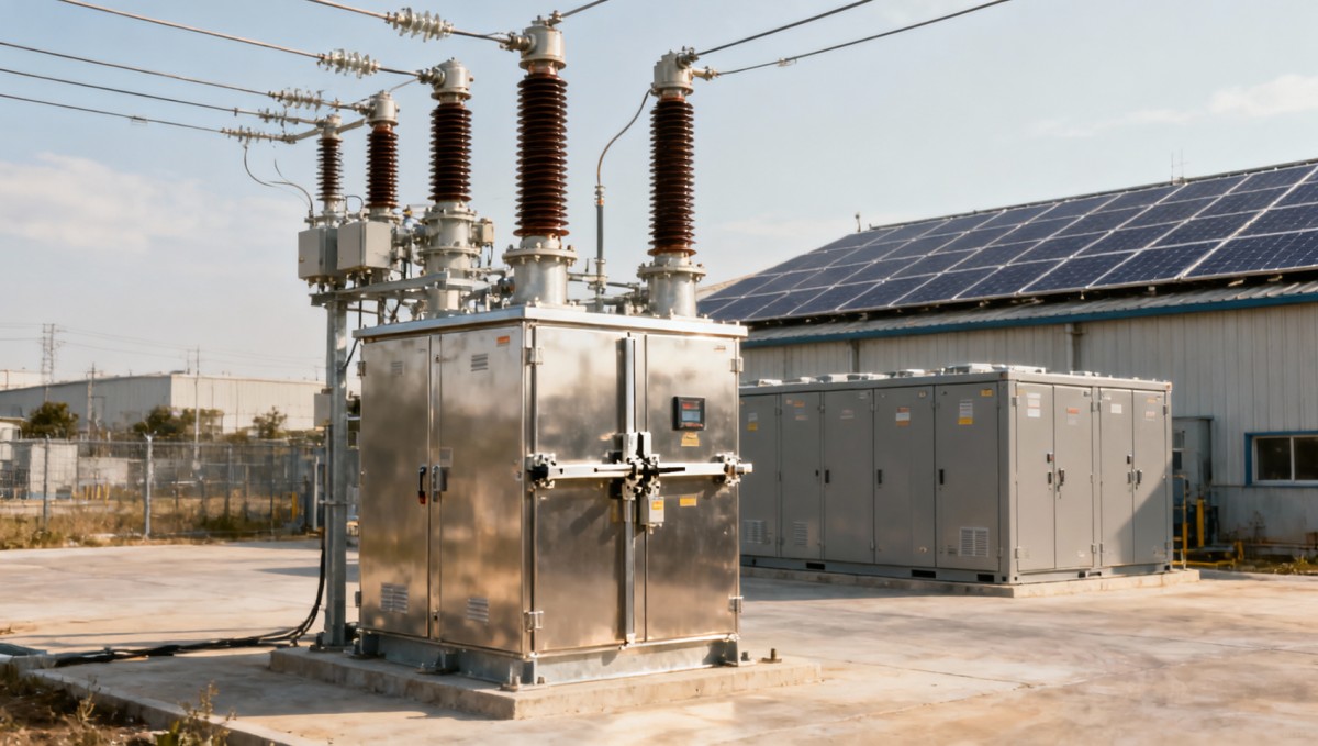
In this arrangement, automation needs to distinguish three conditions: a fault cleared by protection, a faulted section isolated from all sources, and a healthy section eligible for restoration. A breaker trip establishes only the first condition. Isolation requires confirmed device positions and a topology model that includes DER connection points, relevant transformer connections and alternative supply paths.
Switch capability is another constraint. A sectionalizer or load-break switch must not be treated as a fault-interrupting device unless its ratings and application permit that duty. DER can change the current present when an opening command is issued. Switching logic must therefore coordinate with protection rather than assuming the upstream trip has removed all current.
Unknown or conflicting indications should block the affected automatic sequence. An unconfirmed switch position, missing DER status or stale topology update is not a reason to infer successful isolation. The safe response can be to restore a smaller verified section while retaining an automation block around the uncertain boundary.
Restoration is a constrained network calculation
Once the faulted section is isolated, closing a tie can reverse power flow through conductors, regulators and protection zones. DER changes both the steady-state loading and the conditions immediately after energization. A restoration plan is acceptable only if it remains within operating limits and preserves protection performance in the resulting topology.
Pre-fault net load is an unreliable restoration input when DER behavior changes during the outage. A solar-rich section may have imported little power before the fault but require substantially more from the alternate feeder if inverters have disconnected and are waiting to reconnect. Cold-load pickup can increase demand at the same time. Battery behavior depends on dispatch, state of charge, control mode and availability—not simply nameplate power.
Restoration calculations should therefore distinguish gross demand, available generation and expected reconnection behavior. They should also test the consequences of losing the DER contribution used to justify a transfer. If that loss would immediately overload the alternate path, the scheme needs an effective corrective action or a more conservative restoration limit.
Unbalanced distribution power flow is valuable where single-phase DER, uneven loading or long laterals make a balanced model inadequate. Steady-state power flow alone, however, cannot establish relay performance, inverter fault response or island stability. Those questions require appropriate short-circuit, protection and dynamic studies.
A battery does not automatically make a restoration island
A grid-following inverter depends on an established voltage waveform and does not, by itself, provide the reference needed to energize a dead network. Grid-forming capability can support an island, but that capability alone does not establish an approved operating scheme.
Intentional island restoration also requires a defined boundary, load-generation balancing, suitable protection, grounding arrangements, energy sufficiency and a controlled reconnection process. Fault detection becomes especially important because inverter-limited fault current may not operate conventional overcurrent protection as expected.
Battery power and energy impose separate limits. A unit may have enough instantaneous power to energize selected loads but insufficient usable energy to sustain them for the required period. Load steps, motor starting and reserve requirements can constrain the island further. Unless these functions have been engineered and authorized, FLISR should treat the DER installation as a resource subject to its interconnection rules, not as an available black-start source.
Models and communications determine whether automation can be trusted
The minimum useful DER model includes connection location, technology, rating, operating mode, applicable protection settings and disturbance response. For storage, available power and usable energy matter separately. For inverter-based resources, manufacturer-supported fault-response models are more informative than a generic fixed current multiplier.
Model detail should match the decision. A feeder power-flow model can screen transfer capacity and voltage constraints. Protection coordination requires fault-current representations and device operating characteristics. Electromagnetic-transient analysis may be necessary where control interactions or fast inverter behavior determine the outcome; it is not automatically required for every feeder restoration study.
Communications must preserve the meaning of measurements, not merely deliver values. Switch position, DER availability and voltage status need timestamps, quality indicators and defined stale-data limits. Event records require sufficient time alignment to reconstruct operating sequences. A message received successfully can still describe a state that is no longer valid.
Loss of the DER management system or a communications link should have a defined operational consequence. Automation may continue within a conservative envelope based on verified conditions, but it should not credit dispatchable DER support that cannot be confirmed or controlled. Remote commands also need authentication and authorization appropriate to their switching or protection consequences.
Standards establish interfaces—not feeder-wide proof
In the United States, IEEE 1547-2018 addresses DER interconnection and interoperability requirements, including disturbance response and unintentional islanding. IEEE 1547.1-2020 defines associated conformance test procedures. The adopted requirements, utility interconnection rules and actual equipment settings must be identified for the installation concerned.
Conformance does not establish that a particular feeder’s protection coordination or restoration sequence is correct. Equally, support for IEC 61850 or another communications standard does not prove consistent device semantics, suitable end-to-end latency or dependable handling of failed commands. Those properties require system-level verification.
Acceptance testing should challenge the assumptions that can reverse a switching decision: high and low DER output, reverse flow, DER disconnection during a fault, delayed reconnection, unavailable storage, failed switches, stale telemetry and loss of communications. Closed-loop testing with actual controllers or representative hardware can expose timing and state-estimation problems that offline calculations miss.
The decisive evidence is a traceable sequence: protection clears the fault, confirmed switching isolates it from every credible source, and restoration proceeds within validated electrical limits. DER-ready FLISR is demonstrated by that sequence under changing source conditions—not by the presence of a DER interface alone.
Recommended News
- Energy Management in North America: Using Demand Response to Cut Facility CostsOct 26, 2026Explore energy management North America facilities can use to cut costs with demand response. Learn to assess programs, protect operations, and unlock reliable savings.
- China’s First Regional Electricity Market Begins Formal OperationOct 25, 2026Explore China’s first regional electricity market across five regions. Discover what its trading framework could mean for power procurement, contracts and business planning.
- How DER affects fault location, isolation and service restorationOct 21, 2026Explore how DER affects fault location isolation and service restoration. Learn key protection, switching and modeling strategies for safer, more reliable feeder recovery.
- How are cybersecurity requirements shaping the smart grid RTU market?Oct 21, 2026Explore how cybersecurity is reshaping the rtu in smart grid market, from supplier qualification to lifecycle costs. Discover what makes secure RTUs more competitive.
- How does distribution automation differ from SCADA?Oct 21, 2026Distribution automation vs. SCADA: discover how control logic, fault restoration, and voltage optimization differ—and what to evaluate for smarter grid upgrades.
All Categories
Hot Articles
- Green Technology in the Middle East: Key Applications in Energy and WaterNov 01, 2026Explore green technology Middle East applications in solar power, energy storage, desalination, and water reuse—and learn what makes projects succeed.
- World's Largest Liquid Air Energy Storage Project Connects to Grid in GolmudNov 01, 2026The world's largest liquid air energy storage project connects to the grid in Golmud, offering 600 MWh of capacity and 10 hours of discharge.
- Digital Marketing Tools for Brand Awareness: Which Ones Fit Your Goals?Oct 31, 2026Find digital marketing tools for brand awareness that fit your goals. Compare channels, measure recognition, and build a strategy that reaches the right audience.